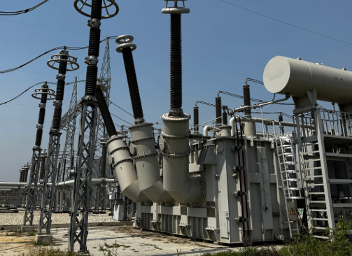



The basic concept of power transformer design has not changed in the last 130 years. Design details and manufacturing concepts are changing based on two factors:
- The environment factor, which has influenced the use of new insulating materials and Distributed Energy Resources (DERs), and
- Economics, which will constantly be a factor in our competitive deregulated marketplace.
An abbreviated version of this paper was written and published about 18 years ago providing insight in the transformer industry of the day [1]. The unabbreviated paper that follows also provides recommendations for design, monitoring and maintenance, which remain valid in today’s industry.
The single most important factor in the life of the transformer is the condition of the insulation system.
A transformer that is properly specified, manufactured, tested and installed should require minimal maintenance throughout its lifetime. The aim of any maintenance program should be to prevent unplanned outages and to extend the life of the transformer. The most important factor in extending the life of power transformers is maintaining the integrity of the oil/insulation system. The different types of transformer preservation systems are the main accessory item responsible for maintaining this integrity, but quite often the least considered and most neglected. This paper will briefly discuss the following items as applied to small, medium and large power transformers:
- The life cycle of a transformer and its dependence on the oil/insulation system and economic factors
- The application and maintenance of the four basic types of transformer preservation systems used on small, medium and large power transformers
- A pro-active diagnostic maintenance plan
- A re-active diagnostic maintenance plan using an event-action item matrix
Basic transformer design technology is over one hundred years old. During these 100 years, transformer technology has advanced and continues to advance but the basic concepts of design, application and protection are essentially the same. R&D concentration for the last fifty years was limited to new materials and manufacturing processes and in the last quarter century, condition monitoring and diagnostics have taken precedence. The transformer technology evolution is dependent upon and restricted by one basic fact – economics or Asset Management.

A CIGRE article published in April 2003 [2] provides a model of the three Es of the past, present and future (Figure 1). This general model is a good example of the factors that determine technological advancements or stagnation within the power transformer industry.
Economics will never be at the bottom of the totem pole model, as long as competitive or deregulated markets prevail. Unless major technological advances are made in transformer design and/or manufacturing, economics will remain at the top of the totem pole for the foreseeable future. So, what is the best plan to obtain a quality transformer at a competitive price that will require minimal maintenance throughout its lifecycle? This depends on the cycles in the life of a transformer.
The Life Cycles of a Transformer
The life cycle of a transformer can be viewed as nine major events that determine the ultimate quality and operational longevity of a power transformer [3]. The events in the order of sequence are shown in Figure 2.
Most end users consider the specification and manufacturing as the most critical stages in obtaining a quality transformer. In many instances the specification, manufacturing and testing of the transformer are thought to be the only critical cycles in obtaining a quality product. This misconception is quite often held by both the transformer end users and manufacturers.

Experience has shown that this misconception all too often results in new transformer failures upon energization, unplanned outages or abbreviated operational life. Quality manufacturers of medium and large power transformers have large capital equipment and human resources costs tied up in the processes necessary to provide an oil/insulation system of the highest possible integrity. The processes of shipment, receiving, storage, installation, operation and maintenance should be equally important in maintaining the integrity of the oil/insulation structure. While these events cannot be totally ignored, the driving factors that minimize the importance of stages 4 to 9 are lack of knowledge, lack of standards and ultimately, the economics.
Consideration of all aspects within each of the transformer life cycles requires considerable human and economic resources. When the necessary resources are utilized by both the end users and manufacturers, the results can be no unplanned outages and large power transformers with an average life span of 30 to 60 years or beyond.
When the necessary resources are applied at the specification cycle through the operations cycle, maintenance becomes the least important and most economic cycle.
Presently, economics remains the dominant factor in purchasing new transformers or maintaining transformers in use. Available resources should be focused on areas that will do the most to prevent unplanned outages and transformer failures.
Quite often the specification, manufacturing and testing of the transformer are thought to be the only critical cycles in obtaining a quality product. Experience has shown that this misconception often results in new transformers failing upon energization, unplanned outages or abbreviated operational life.
The single most important factor in the life of the transformer is the condition of the insulation system. This statement is emphasized in many different forms by all power transformer manufacturers. With this in mind, resources may be focused in the following two areas for both new transformers and transformers in use:
- Application and maintenance of the transformer preservation system
- An economic diagnostic maintenance plan
Application and Maintenance of Transformer Preservation Systems
Medium and large power transformers have four basic types of transformer oil/insulation preservation systems. There are many variations of the four systems described in this paper, based on differences in manufacturer designs or end user field modifications. The intent of this paper is to supply the basics for application, clarify possible misconceptions and provide quality pointers to avoid operational problems. To the best of my knowledge, there are no domestic or international standards for the application or design of transformer preservation systems. The four basis systems are as follows.
- Sealed-Tank System
The sealed-tank system is one in which the oil/insulation system is sealed from the atmosphere by the tank/cover assembly and the gas plus the oil volume remains constant over a temperature range. Initial shipment from the manufacturer and/or prior to energizing in the field, the transformer gas space is normally purged with an inert gas such as dry nitrogen and sealed with a positive dry gas pressure. The sealed-tank system is normally designed with sufficient gas space to accommodate the expansion and contraction of he oil due to thermal cycling with varying loads.
Various accessory items may be provided on the external tank wall gas space as a regulating device to protect the tank structure from excessive positive or negative pressure and to regulate the positive/negative pressure within a designated range. The most common device is a pressure-vacuum bleeder, with sampling valve, normally preset at the factory based on the manufacturer’s standard design or the customer’s specification. Transformer users should be fully aware that the sealed tank system cannot assure that the tank will not systematically breathe (take in atmosphere) or system atically expel gases contained in the transformer gas space. This can and will occur due to changes in ambient temperatures in combination with load or absence of load. A common misconception is that the sealed tank system will prohibit oxygen and moisture from being absorbed into the oil/insulation system. In many circumstances, it will not.
Benefits:
- A practical and efficient application for small power transformers that do not experience extreme temperature fluctuations. It is recommended that sealed-tank systems be limited to transformers with maximum voltage levels of 35,000 volts.
- Economical for the manufacturer and end user, both from the application (size) and maintenance standpoint
Recommendations:
- DBPC oil inhibitor should be specified and maintained at 0.15% to 0.30% by total weight of oil. DO NOT exceed 0.34% DBPC by weight of oil.
- Sealed-tank systems may frequently operate in an energized or deenergized state while having a negative pressure (partial vacuum) above the oil level. When the transformer is energized or de-energized and has a negative pressure head above the oil level, DO NOT obtain an oil sample from the transformer. It is recommended to place the following warning labels at all oil valves on all sealed-tank transformers:
Warning – Never open the transformer oil sampling valve if there is a vacuum on the transformer tank. Check the pressure-vacuum gauge on the oil preservation system to be certain there is a positive pressure reading. If you open the sampling valve when there is a vacuum on the tank, air bubbles may be drawn into the transformer. Air bubbles may cause an insulation failure and result in equipment damage, severe personal injury or death.
- With the transformer de-energized, all welds and gasketed joints above the transformer oil level should be periodically checked for gas leaks.
- Inert Gas-Pressure System
The inert gas-pressure system is one in which the interior of the main transformer tank is sealed from the atmosphere, over the temperature range specified, by means of a positive pressure of inert gas maintained from a separate inert gas source and reducing valve system. The inert gas most commonly used is dry nitrogen. Gas blanketed transformers which are properly maintained will eliminate the possibility of atmosphere being drawn into the transformer tank. Because of this and the overall physical size of an inert gas-pressure system, many utilities prefer this system for small and medium power transformers.
Rcommendations:
- It is important for systems that apply constant gas pressure to the transformer to have scheduled periodic maintenance. All seals in the transformer gas space and in the preservation system must be maintained for the system to function properly. In addition to the many seals in the transformer gas space, there are numerous seals within the common gas-pressure systems such as pressure regulator fittings, valve fittings, piping connections, and gas bottle connections.
- Do not use teflon sealing tape on gas pressurized fittings. Excess teflon can be torn away and will clog the small orifices in the system. This will disable the system.
- Never use SF6 gas in a transformer gas blanketed system. SF6 gas is three to four times more soluble in transformer oil than either nitrogen or air. SF6 gas has an extremely high probability of producing gas bubble evolution in transformer oil. In addition, SF6 in the presence of arcing and corona discharges will
- produce corrosive by-products.
- Argon gas is sometimes used in gas blanketed systems. I would NOT recommend argon in place of dry nitrogen. Nitrogen is more common and abundantly produced. In addition, most dissolved gas analysis (DGA) will indicate argon as being oxygen unless the testing laboratory is told to check for argon.
- Transformers with a constant gas pressure on the oil surface (inert gas-pressure system) are more susceptible to gas bubble evolution and failures during startup and shutdown. A startup and shutdown procedure using manual or modifiedautomatic cooling controls should be in place for all inert gas-pressure transformers. The object of the procedure should be to circulate the oil past the interface with the gas blanket to speed the release of nitrogen (inert gas) from the oil. This should be accomplished with as gradual temperature increases during startup as possible and as gradual temperature declines during shutdown as possible. Transformers with pumps (forced oil) must also consider the potential of static charge buildup if oil circulation becomes excessive at lower temperatures during the startup or shutdown procedure. Because of the potential for gas bubble evolution in gas pressure systems, I would not recommend inert gas-pressure systems on transformers with a voltage higher than 138,000 volts.
- Inert gas-pressure systems that malfunction can cause the transformer gas space to have negative pressure. I recommend that gas pressure systems have warning labels at all oil valves as follows:
Warning – Never open the transformer oil sampling valve if there is a vacuum on the transformer tank. Check the pressure-vacuum gauge on the oil preservation system to be certain there is a positive pressure reading. If you open the sampling valve when there is a vacuum on the tank, air bubbles may be drawn into the transformer. Air bubbles may cause an insulation failure and result in equipment damage, severe personal injury or death.

- Conservator System
The conservator system is one in which a separate oil expansion tank allows the main transformer tank to remain full of oil despite expansion or contraction of the oil with temperature changes. The expansion tank also reduces the rate of oxidation of the oil, primarily because less oil surface is exposed to the air and because of the reduced temperature of the oil that is exposed to air. In most cases the expansion tank is mounted on the LV side of the transformer tank, above the level of the transformer cover.
Common accessories that may be provided with the conservator expansion tank assembly are as follows:
- The pipe between the expansion tank and transformer tank may utilize a trap (with drain plug) which retards the oil circulation between tanks and permits the draining of condensation that may collect in the pipe.
- A relief device mounted on the transformer cover with an elevation such that the relief device is above the maximum oil level in the expansion tank.
- Oil level indicator, oil sampling valve, and a handhole.
- Gas accumulator device mounted in the piping between the expansion tank and transformer.
- Open air breather or a dehydrating breather. A dehydrating breather is recommended.
Recommendations:
- Many expansion tanks are not braced for full vacuum although the main transformer tank may be good for full vacuum. Always follow the manufactures instructions for filling the main transformer tank and the conservator tank.
- Large power transformers are often initially installed or maintained by a hot oil circulation process. A common field mistake is to fill the transformer or its expansion tank to the “normal” or 25°C level even if the hot oil is at 80 to 90°C. This will present future problems. Manufacturer’s instructions should be adhered to for determining proper oil levels based on oil temperature.
- DBPC oil inhibitor should be specified and maintained at 0.15% to 0.30% by total weight of oil. DO NOT exceed 0.34% DBPC by weight of oil.
- A dehydrating breather should be used rather than an open-air breather.
- A variation of the conservator expansion tank is known as the gas-oil seal expansion tank. The gas-oil seal expansion tank is an enlarged expansion tank with a constant positive inert gas pressure above the oil level in the expansion tank. I recommend a conservator-diaphragm system rather than the gas-oil seal expansion tank for all transformers with voltages above 138,000 volts.
- Conservator-Diaphragm System
As defined by ANSI/IEEE C57.12.80 [4], the conservator-diaphragm system is one “in which the oil in the main tank is completely sealed from the outside atmosphere, and is connected to an elastic diaphragm tank contained inside a tank mounted at the top of the transformer. As the oil expands and contracts within a specified temperature range the system remains completely sealed with an approximately constant pressure.” Contact between the oil and the atmosphere is prohibited by the elastic diaphragm tank (air cell) in the expansion reservoir.
More so than any of the previous preservation systems listed in this paper, in theory and practice this system can assure that gases and moisture from the atmosphere will not come in direct contact with the transformer oil/insulation system. All skeptics should note the word “direct” in the last statement as being a form of disclaimer.
Conservator-diaphragm systems all operate on the same principles but vary in name and mechanical aspects from one supplier to another. While the conservator-diaphragm system is possibly the best system to extend the operational life of large power transformers, individual end-users should start at the specification stage to be sure that this system is the best fit for their environmental, maintenance and asset management plans.
Recommendations:
- Many conservator-diaphragm expansion tanks are not braced for full vacuum although the main transformer tank may be good for full vacuum. Always follow the manufactures instructions for filling the main transformer tank and the conservator-diaphragm tank. In addition, DO NOT pull vacuum on a conservator diaphragm tank specified good for full vacuum unless the conservator diaphragm and all accessories with diaphragms, such as gas detectors, are totally isolated from the negative pressure (vacuum).
- Some older transformers and possible new transformers are designed such that the minimum oil level in the conservator-diaphragm tank is physically located below the top of the main transformer tank. When this occurs, a negative pressure can develop in the top of the main transformer cover and all associated fittings/parts that would normally contain oil. When this occurs, it is very common for gas accumulator relays to alarm due to the accumulation of atmosphere breathed in through fittings, gaskets or weld leaks on the top of the transformer cover. The minimum oil level in the conservator-bladder tank should always be located above the highest oil filled accessory located on the transformer cover. This does not include self-contained oil accessories such as HV or LV bushings.
- Conservator-diaphragm tanks may be supplied with free breathers or a filter/dehydrating breather. It is recommended to use a filter/dehydrating breather to protect the diaphragm material from air borne pollutants and moisture.
- Conservator-diaphragm systems should have a gas-detector relay mounted on the transformer cover. It is also recommended that a gas/oil-flow detector be provided in the piping connection between the transformer main tank and the conservator tank.
- DBPC oil inhibitor may be used to retard oxygen absorbed during maintenance outages requiring opening of tank seals. DBPC oil inhibitors should not be used to forgo the maintenance required to maintain the transformer seals and the integrity of the conservator diaphragm system.
- The conservator diaphragm may be made from synthetic rubber or other elastic materials. The diaphragm (air cell) is often damaged during transportation, field installation or during maintenance operations. It is not uncommon to weld on the surface of the conservator tank during the initial field installation or during a maintenance outage. All diaphragm material should have sufficient clearance or be insulated from the tank weld area so as not to be damaged by the welding.
- Final oil filling of transformers with conservator-diaphragm systems often requires a heated oil circulation process. Manufacturers instructions for filling the conservator tank based on oil temperature should be adhered to.
An Economic Diagnostic Maintenance Plan
The old cliché “beauty is in the eye of the beholder” can very practically be applied to “Economics is in the eye of the beholder”. In pre-deregulation days, many utilities had top executives and managers with engineering backgrounds. Today, top managers have financial backgrounds. In plain English, in a deregulated market, operations are expected to run at maximum capacity and minimum maintenance [5].
Prior to deregulation, the most common term applied to transformer maintenance programs was Preventative or Scheduled Mainten ance. With the advent of deregulation within the power industry, many different names have been applied to transformer maintenance. Examples are Reliability Centered Maintenance (RCM), Condition Based Maintenance (CBM), Predictive Maintenance, Condition Monitoring Maintenance (CMM), Computerized Maintenance Management System (CMMS).
I believe that there are only two basic types or categories of transformer maintenance: Pro-active and Re-active. In practice, present day transformer maintenance procedures are a combination of pro-active diagnostics combined with re-active maintenance. This combination can be reliable and economical only if the necessary diagnostic skills are available and the re-active procedures are applied properly and timely [6].
The following diagnostic maintenance plans are an attempt to provide a general pro-active and re-active plan. The intent of both plans is to have or obtain a “genetic signature” of the transformer. The “genetic signature” being the initial diagnostic test values from which to determine the future operational integrity of the transformer. Once again, these plans or any diagnostic maintenance plan cannot succeed without the proper diagnostic skills and proper/timely maintenance procedures.
In practice, present day transformer maintenance procedures are a combination of pro-active diagnostics and re-active maintenance.
A Pro-Active Diagnostic Maintenance Plan
For any diagnostic maintenance plan to be pro-active it should contain two elements. First, determine the criterion (genetic signatures) to be used to monitor the operational integrity. Second, determine a schedule for periodic re-testing or monitoring of the chosen criterion. The schedule for re-testing, monitoring and/or possible maintenance should be based on the end user’s asset management plan and the available diagnostic criterion.
Transformers with identical name plate ratings but from different manufacturers can have large variations in their “genetic signature(s)”. These differences occur due to design, materials, factory processes and procedures. Initial diagnostic testing to obtain the “genetic signature” should begin at the initial field installation. These test results can then be compared to factory test results. An aged “genetic signature” can be obtained at any point during the operational life of the transformer if there were no previous diagnostic tests available. This will make the evaluation process more difficult. Complete “genetic signature” testing requires both de-energized and energized tests as follows.
In pre-deregulation days, many utilites had top executives and managers with engineering backgrounds. Today, top managers have financial backgrounds. In other words, in a deregulated market, operations are expected to run at maximum capacity and minimum maintenance.
De-energized oil-filled transformer testing (genetic signatures) includes:
- Ratio tests (TTR) on all windings and all tap positions
- Insulation power factor
- Single phase exciting current measurements
- Insulation resistance test from each winding to ground and to the other windings
- Measure the core resistance to ground
- Power factor and capacitance tests on all condenser bushings
- Sample oil for both an oil screen test and dissolved gas analysis (DGA)
Energized transformer testing includes:
- After the transformer is energized and carrying load for a minimum of 24 hours, do a complete infrared scan. A complete infrared scan should include all wall surfaces including the cover, all external bushings, external bushing connections, all individual coolers, transition compartments, load tap changer compartment, control cabinet, power supply connections and all other accessory devices. A log of infrascan results should include percent of load and ambient temperature at the time of the infrared scan. This infrared thermography scan should be preformed at minimum once per year.
- After the transformer is energized and carrying load for a minimum of 24 hours, take an oil sample for dissolved gas analysis (DGA). Recommend that DGA be performed at a minimum of twice per year. More frequent DGA tests may be required dependent upon the type of gases being generated and/or their rates of acceleration.
- A visual inspection should be made at least twice a year. Inspection should include checks on all the following:
- Oil and/or gas leaks at all transformer seals, auxiliary tanks, LTC compartments, individual coolers and weld seams
- Transformer preservation system
- Oil level in the main tank, auxiliary tanks, LTC compartment, and bushings
- All control cabinets
A Re-Active Diagnostic Maintenance Plan
A re-active diagnostic plan should begin with establishing the same “genetic signatures” that are used in the pro-active plan. The basis for all future actions taken will partially rely on the data (“genetic signatures”) obtained from both the de-energized transformer testing and the energized transformer testing. The difference is that future outages for testing and/or maintenance are NOT scheduled based on a preset pre ventative maintenance plan. Planned outages or unplanned outages are based on events in combination with on-line diagnostic tests, data collection and on-line monitoring if applicable.
The event-action item matrix that follows is for a typical generator step-up transformer rated OA/FOA/FOA by old standards or ONAN/ODAF/ODAF by new standards. End users should determine events and action items based on the following:
- type of their transformer
- system requirements
- asset management plans
Transformer Action Requirements
| Event | Date | % Load | Visual Inspection | Internal inspection | Infrared scan | Cooling status and all temeprature indicators | DGA | Oil screen | Particle and metal analysis | Degree of polymerization | On-Line PD and vibration |
| Visual inspection | DR | DR | DR | NA | DR | DR | DR | DR | DIN | NA | DR |
| Overload | DR | DR | DIN | DIN | DR | DR | DR | DIN | DIN | DIN | DR |
| Overvoltage | DR | DR | DIN | DIN | DIN | DR | DR | DIN | DIN | DIN | DR |
| Through-fault | DR | DR | DR | DIN | DIN | DR | DR | DIN | DIN | DIN | DR |
| Environmental | DR | DR | DR | DIN | DIN | DR | DR | DIN | DIN | DIN | DR |
| Transformer trip | DR | DR | DR | DIN | NA | DR | DR | DR | DIN | DIN | DR |
| Transformer alarm | DR | DR | DR | DIN | DIN | DR | DR | DIN | DIN | DIN | DR |
| Loss of control power | DR | DR | DR | DIN | DR | DR | DR | DR | DIN | DIN | DR |
| Pump problem | DR | DR | DR | DIN | DIN | DR | DR | DR | DR | NA | DR |
| Bushing problem | DR | DR | DR | DIN | DIN | DR | DR | DIN | DIN | NA | DR |
| Bus duct problem | DR | DR | DR | NA | DR | DR | DR | DIN | NA | NA | DR |
| Before maintenance | DR | DR | DR | DIN | DIN | DR | DR | DR | DIN | NA | DR |
| After maintennace | DR | DR | DR | NA | DR | DR | DR | DR | DIN | NA | DR |
DR = Data Required
DIN = Determine if Necessary
NA = Not Applicable
DGA = Dissolved gas analysis
Note: Events and Transformer Action Requirements should be determined by the type of transformer, system requirements, system anomalies and the asset management plan.
Conclusion
A realistic maintenance plan begins at the specification stage. A successful plan will combine operational objectives with human resources, equipment environment, and asset management objectives. Considerations for the addition of optional on-line monitoring equipment at the specification stage are very important for any re-active maintenance plan. Monitoring equipment applied at the design stage will be more reliable due to pre-designed locations, application and testing on the transformer prior to shipment.
The majority of engineers responsible for design, operations or maintenance functions prefer scheduled preventative maintenance for critical equipment rather than a re-active maintenance plan. The partially deregulated power industry and the end user markets for electrical power do not lend themselves to preventative maintenance or prescheduled outages. The majority of power transformers presently and in the future will combine pro-active diagnostics with re-active maintenance.
References:
[1] P.J. Pillitteri, “Back to Transformer Basics – Economic Diagnostic Maintenance,” Proceedings of the IEEE SoutheastCon 2006, Memphis, TN, USA, 2006, pp. 51-57
[2] CIGRE-ELECTRA, April 2003, Joint Advisory Group SC15/D1-TF03, “Emerging Technologies and material changes”
[3] Paul Pillitteri, “Life Cycle of a Transformer,” VA Tech Elin USA, J.W. Harley Monitoring Conference 1997
[4] ANSI/IEEE C57.12.80, Terminology for Power and Distribution Transformers
[5] PowerMarketers, The Power Report, “Blackout Reignites Deregulation Debate”, Akron Beacon Journal, Ohio, August 24, 2003
[6] Terry Krieg, “Transformer monitoring: Key to cost effective asset management,” Electrical World, March/April 2001

Paul Pillitteri has been in the medium and
large power transformer industry for 50 plus years. He has worked for three leading transformer manufactures prior to becoming a transformer consultant for the last 20 years. His experience covers most areas of power transformers including design, manufacturing, testing, repair/refurbishment, field service,
and facility operations manager.

This article was originally published in the October 2021 issue of the For the Love of Bushings: Critical Materials & Components magazine.
View Magazine